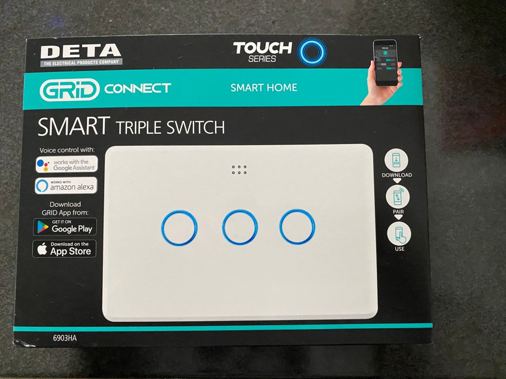
I’ve been using the Deta Grid Connect 1 and 2 gang light switches with Home Assistant for about 6 months now – as mentioned in this post. The 3 and 4 gang switches have finally arrived, and having picked one up from Bunnings, I was keen to get it setup and the firmware replaced with my own.
As mentioned in that previous post, replacing the firmware with ESPHome, your own firmware, or Tasmota has two methods. The first method is to use tuya-convert over WiFi, and the second method is to use the headers on the circuit board to plug your own leads in and upload firmware through a serial connection. Unfortunately, the good people at Deta have removed the headers on the circuit board, and changed the key used by the firmware rendering tuya-convert unusable.
It is only a matter of time though before tuya-convert is updated which will enable a wireless push of new firmware to the device. Luckily though, even without the headers, you can still use a serial connection to the board. The difficulty though, is you either need to solder your own leads on or be a little dexterous. As I mentioned on the earlier post, you need to provide power and ground to the board; you need to connect your serial programmer’s TX and RX; and you need to pull RST and GPIO0 to ground, release RST to boot the device and then release GPIO0 for programming mode.

In order to avoid soldering, or needing 4 hands, you can connect power and ground to the bottom pins on the board. You need to supply 5V though, as the pin doesn’t connect directly to VCC on the chip, rather it connects to the input side of the voltage regulator. So providing 5V on the pin gets you 3.3V on the chip. I used a bread board power supply to get the 5V, and I shared the ground on the bread board power supply to my programmer.
I then used a couple of ground connected leads to hold against RST and GPIO0 to reboot the device. Releasing RST boots the device, and then releasing GPIO0 a few seconds later enables programming mode.
Once in programming mode, I used a little header block with 2 pins bent away, and connected them to TX and RX on my programmer. I then simply held it against the TX and RX pins on the chip while pushing firmware through the programmer.

Once the firmware had uploaded, I released the TX and RX pins, and then pulled RST to ground momentarily to boot the device.
The firmware I pushed to the device supports OTA (over the air) updates, so hopefully that was only a one off activity! The good news is though, you only ever have to hold 2 pins against the chip at any one time in your hand – so its not too difficult even without the header area on the board.
This sometimes takes a few attempts. Sometimes it works first time, sometimes I might have the timing slightly off, or I may not quite have the pins in contact. So be prepared to give it a couple of attempts.
Edit (28/09/2020): a friend and I refined the process today so there are tidier instructions below. This was done using Tasmota’s Windows tool to push a Tasmota image.
- Click Flash Tasmota (or run esptool.py, or tool of choice). Actually start the upload.
- Pull RST and GPIO0 to GND
- Wait 2 seconds
- Release RST
- Wait 2 seconds
- Release GPIO0
- Connect TX and RX
So basically we clicked the upload button before we had any cables connected – although the USB programmer was already plugged in to the computer. After clicking upload, we reset the device with RST and GPIO0 both set to ground – released RST – then released GPIO0. After that, then we held TX/RX against the pins coming from the programmer, and the tool picked up and started the upload.
~ Mike

Hi Mike,
I’ve just purchased one of these and while the above makes some sense, I don’t understand all of it… any chance you could explain and/or film a little? Just mostly need some advice with regards to boot/program mode and process…
Just confirming I finally worked it out and have successfully flashed a 4 gang switch.
Appreciate this guide, was great the 4 gang is slightly different although the above pictures are still relevant.
Cheers
Awesome – good to hear. I’ve not unboxed a 4-gang yet, but good to hear its working.
How did you do the 4 gang one – I can’t get it to work
What did you do differently with the 4 gang one – you noted it was slightly different – I couldn’t get it to flash for some reason.
Hi Steve,
I’ve done it a couple of times now, it’s exactly the same as the 3 gang describe only the board looks different.
Can you get it to see the ESP? Or are you having a trouble getting it connected?
I’ve not yet flashed my 4-Gang, I’ll be doing that tonight, but I’ve successfully flashed half a dozen different tuya’s over the last 2 days via OTA, I have three of these and several older sonoffs that need to be done serially.
Hi – my usb to serial adapter has a 3.3v pin and 5v. I connected the 5v to my breadboard then connected a jumper lead to the 5v pin on the board per Mike’s picture. Then connected ground of usb to breadboard and jumper wire from breadboard to ground per Mike’s piacture. This gave the board power as the Led lights came on. Then I connected a jumper from ground (negative on breadboard) to rst pin and the lights in the board went out. Then I connected a jumper from ground to the goio00 pin and the led on the board came on steady. I released the rst and then released the gpio00 3-8 seconds Later (tried different times) but as soon as I pulled the lead of gpio00, the led light on the board went out. Then I connected the rx in usb to Tx on board and Tx on usb to rx on board. (Actually tried vice Versa as well and that didn’t work either) While holding the ex/Tx pins in place, I clicked Tasmotise on tasmotiser after having selected the right com port (com3) and the top Tasmota bin release plus the tick box of backup and flash. The backup part my have worked as it put a file on my pc but the download firmware part says failed to connect to esp times out waiting for packet header and sometime I got invalid head of packet ox4f. Either way, nothing downloaded as nothing moved off the zero % in the download bar. Not sure what I’m doing wrong . Strangely, I was able to push the WiFi SSID and password to the device as it said 110kb pushed.
I’ve tried for about 12 hours to get this to work – all my it’s capable devices work but not this one. I’ve tried everything – is there someone I can mail my device to with paid return mail to see if they can make it work. It’s not going into flash mode.
Howdy, contacted you directly.
Hi how did you get it to work? I’ve got the same problem.
Thanks
Hi Mike. Wondering if the individual switches be used to control other devices? For example. I’d like to replace a single light switch with a 3-gang. First button will control the existing light via the current wire and give the switch its power, the other two buttons programmed (in home assistant) to run another device elsewhere in the house (maybe trigger a HA automation). Would this type of config be possible with ESPHome or can they only control wired lights?
Cheers.
Hi Andrew – you could leave one of the output light connections not connected to anything – the software running on the controller doesn’t actually know if there’s something there. You can do a lot of cool stuff with them just as a switch.
I’ve actually got one connected to a LIFX wifi light. However, its programmed so that when I press the wall switch, it doesn’t actually power off the light, but rather tells HA to inform the wifi bulb to turn off (but it stays powered). If I then hold the light switch down for 3 seconds, it actually powers the circuit off. I’ve got a friend with one where if you hold the button down, it tells HA to turn off all lights.
Hi Mike, first off thank you for your posts. I’ve just flashed some switches with ‘spare’ gangs just like above.
First time tasmota user and hoping you might tell me more about how to make smart buttons out of the spare gangs? Should I remove the corresponding relay from the template and just leave the button?
I’ve seen talk around Switch mode but unsure how to apply it to a specific gang and utilise button hold modes.
Otherwise everything is happy in home assistant 😀
Cheers,
Linton
Hi Mike – have you managed to flash the Deta light and fan switch with Tasmota – I managed to get it flashed with Tasmota and it works with home assistant perfectly – I used the Blakadder code for the gpio’s etc – however, while it works from a web browser, it doesn’t work from the actual device – touching the device does not work – wondered if you encountered the same issue.
I used ESPHome… the Home Assistant integration works perfect and also the buttons on the device. Using the ‘Cloud’ integration with Home Assistant I also have voice control.
Hi Steve. I am currently trying to flash the Deta light and Fan switch with Tasmota. Are you able to confirm the correct 5v and GND pins on the board as to me they are different to the above picture. When measured the top 2 right pins look to be GND and bottom 2 rights pins look to be 5v when measured with board plugged into main DETA module. Applying 5v from my serial adaptor does not power up the board. Any help appreciated.
Thanks.
Thanks for posting this, Mike – I could have done it without it.
Thanks Chris – glad it helped.
Just wanted to call out and say that your advise was golden – I bought these from my local bunnings – First one went fine with OTA – second one had the new firmware that had the same issue – Your instructions for wiring were perfect. I just finished documenting my process for my own prosperity but just wanted to call out that it was awesome.
Thanks Nathan – glad it helped!
Just reaching out as has others. Great stuff Mike, much appreciated. I’ve been holding off doing an old Sonoff 4ch pro and after doing one of my 2-gangs (serially following your instructions), I went ahead and did a few more, including that Sonoff (which was a tad harder TBH).
Awesome!
Just finished getting an electrician to install 24 DETA smart switches including 1, 2, 3 and 4 gang. All flashed thanks to your guides. Working brilliantly. Thanks for putting this information out there.
I did have one question tho, I assume it’s a simple answer. In Home Assistant, it appears as a switch and a status entity. I am assuming the status is the WiFi signal strength?
Glad to hear! Not sure about the status entity – I’m not using ESPHome on mine.
I managed to flash my 3 Gang Switch!
Thanks for the instructions. I ended up soldering on to Ground, RST, GPI0 with some little bare ends. Makes the boot up process easier.
I cant figure out the GPIO settings:
Button1 = GPIO16
Relay2 = GPIO14
Relay3 = GPIO12
ESPHome warns me about using GPIO6-11 and the others dont seem to work?
Here is my work in progress yaml
substitutions:
devicename: esppowderroom
upper_devicename: Powder Room
friendly_name: “Powder Room Switch”
button1_name: “Heat” ### Left or Top
button2_name: “Fan” ### Middle
button3_name: “Light” ### Right or Bottom
#################################
esphome:
name: esppowderroom
platform: ESP8266
board: esp01_1m
wifi:
ssid: !secret wifi_ssid
password: !secret wifi_pass
# Enable fallback hotspot (captive portal) in case wifi connection fails
ap:
ssid: “Powder Room Switch”
password: “Powder Room Switch”
captive_portal:
# Enable logging
logger:
# Enable Home Assistant API
api:
password: !secret api_pass
ota:
password: !secret ota_pass
sensor:
– platform: uptime
name: $upper_devicename Uptime
– platform: wifi_signal
name: $upper_devicename WiFi Signal
update_interval: 15s
#################################
status_led:
pin:
number: GPIO4
inverted: True
output:
# Button1
– platform: gpio
pin: GPIO3
id: relay1
# Button2
– platform: gpio
pin: GPIO14
id: relay2
# Button3
– platform: gpio
pin: GPIO12
id: relay3
light:
– platform: binary
name: $upper_devicename $button3_name
output: relay3
id: light1
switch:
– platform: output
output: relay2
name: $upper_devicename $button2_name
icon: “mdi:fan”
id: fan1
– platform: output
name: $upper_devicename $button1_name
output: relay1
id: heat1
– platform: restart
name: $upper_devicename REBOOT
# Buttons
binary_sensor:
# Button1
– platform: gpio
device_class: heat
pin:
number: GPIO16
mode: INPUT_PULLUP
inverted: True
name: “${button1_name} Button”
#toggle relay on push
on_press:
– logger.log: “GPIO HEAT pushed”
– switch.toggle: heat1
Brilliant!
I figured it out with a hour more of Guess and Check…
Here is the final working config (tested in prod for 2 days):
substitutions:
devicename: esppowderroom
upper_devicename: Powder Room
friendly_name: “Powder Room Switch”
button1_name: “Heat” ### Left or Top
button2_name: “Fan” ### Middle
button3_name: “Light” ### Right or Bottom
#################################
esphome:
name: esppowderroom
platform: ESP8266
board: esp01_1m
wifi:
ssid: !secret wifi_ssid
password: !secret wifi_pass
# Enable fallback hotspot (captive portal) in case wifi connection fails
ap:
ssid: “Powder Room Switch”
password: “Powder Room Switch”
captive_portal:
# Enable logging
logger:
# Enable Home Assistant API
api:
password: !secret api_pass
ota:
password: !secret ota_pass
sensor:
– platform: uptime
name: $upper_devicename Uptime
– platform: wifi_signal
name: $upper_devicename WiFi Signal
update_interval: 15s
#################################
output:
### Button1
– platform: gpio
pin: GPIO5
id: relay1
### Button2
– platform: gpio
pin: GPIO14
id: relay2
### Button3
– platform: gpio
pin: GPIO12
id: relay3
light:
– platform: binary
name: $upper_devicename $button3_name
output: relay3
id: light1
switch:
– platform: output
output: relay2
name: $upper_devicename $button2_name
icon: “mdi:fan”
id: fan1
– platform: output
name: $upper_devicename $button1_name
output: relay1
id: heat1
– platform: restart
name: $upper_devicename Restart
# Buttons
binary_sensor:
### Button1
– platform: gpio
device_class: heat
pin:
number: GPIO16
mode: INPUT_PULLUP
inverted: True
name: “${button1_name} Button”
### toggle relay on push
on_press:
if:
condition:
switch.is_off: heat1
then:
– switch.turn_on: heat1
– delay: 600s
– switch.turn_off: heat1
else:
– switch.turn_off: heat1
### Button2
– platform: gpio
pin:
number: GPIO04
mode: INPUT_PULLUP
inverted: True
name: “${button2_name} Button”
### toggle relay on push
on_press:
if:
condition:
switch.is_off: fan1
then:
– switch.turn_on: fan1
– delay: 600s
– switch.turn_off: fan1
else:
– switch.turn_off: fan1
### Button3
– platform: gpio
device_class: light
pin:
number: GPIO3
mode: INPUT_PULLUP
inverted: True
name: “${button3_name} Button”
### toggle relay on push
on_press:
– light.toggle: light1
Added some updated comments to help with the flash process.
Hi Mike,
has the OTA option been updated yet as I am not one to play around with wires and solder (eyes are not steady or great)
Thanks heaps for this post! I never would have tried starting the flashing software before having it in program mode, but worked a treat and freed up hands a little more.
@Giscal – I purchased a Deta 4gang on about 21/10/2020 and tried to flash OTA using Tuya Convert (to be honest I didn’t try for long because I didn’t expect it to work). Then flashed it via serial as the post talks through.
@ Michael Bonny or any other ESPhome users,
Would you be able to post your (code formatted) ESPhome configuration for the 4 gang (or otherwise 3 gang) device? I have used ESPHome before for other devices but I’m getting errors on the config. I tried to use the code posted by Michael Bonny above but the yaml formatting doesn’t show properly on this site and it might be why I’m getting errors. Could someone post a formatted config (e.g. GitHub, google docs, whatever!)
This blog post gets lots of links to it, I’m sure it would help other enthusiasts too.
try here: https://drive.google.com/file/d/1tonawVNVdI9UuEWv4XroITbIhUOhopm1/view?usp=sharing
Any ideas how the 5V and Ground pins differ for the Light and Fan controller? I can’t seem to power up the board but have successfully done 4 gang and the dual power points.
Suspecting they need a higher voltage?
Tom the light and fan controller still uses 5v to power the board but the pin locations are different.
I have the light and fan controller working in home assistant but cant seem to figure out the correct spped_value_template in mqtt config for home assistant to give the correct feedback of what speed it is running.
Thank you Darren!!! For those who find themselves in the same predicament, move the GND pin one to the left in the photo above for the Light and Fan controller.
I’m using Homebridge, but it also uses mqtt. I will let you know if I get the fan speed working.
Thanks again 🙂
Thanks Tom. I have the fan speed working through home assistant and mqtt it’s just that home assistant doses not know what speed it’s going which I am pretty sure is done through the speed_value_template. Have tried asking on a few forums but have not had any replies.
I have the 4 gang wall switch and have successfully flashed it with HAA. Thanks for the tutorial
Can anyone help me out with GPIO designations for the 4 gang switch so that I can write the JSON config.
Thanks
Looks like the GPIO designations for the 4 gang are
Relay 1 = 05
Relay 2 = 14
Relay 3 = 12
Relay 4 = 15
switch 1 = 16
Switch 2 = 04
Switch 3 = 03
Switch 4 = 13
Still haven’t figured the LED status light but am guessing GPIO 1. I’ll test and respond if it works.
Thanks Todd – haven’t looked for the status LED on the 4 gang, but I recall with the others you had to pull it to ground to light it up.
the LED status light is on GPIO 0 and does need to be pulled low to enable.
Hi Mike,
Do you think that this is doable for someone with no electrical experience? I don’t have the AVR Programmer or the breadboard/wires but the tuya-convert issue doesn’t look like it’ll be resolved any time soon. You mentioned in this blog post that you had to use an external power source and not the one from the programmer? If so that’ll be another component that I have to pick up.
Thanks
Hi Mike,
Many thanks for the post, got it working just this morning (after spending way too much time on it last night :-))
Perhaps worthy of note, I had to swap my RX/TX => TX/RX (i.e. RX on serial converter is TX on DETA)
And for those of you wondering here are the GPIO settings: https://templates.blakadder.com/deta_6903HA.html
great help!, thanks a lot!
Brilliant, glad it helped. Yeah always a good check with the converters as it’s not always obvious what they intend with the labelling.
Is it possible to turn off the LED indicators in the switch to use these in a bedroom?
Thanks for this post, I’m just entering the murky waters of Australian certified Zigbee mains stuff…Seems that Arlec have the market sewn up with the Mercator and Deta stuff…I’m really liking the IKUU aesthetics, so am heading down that route to start! I look forward tos eeing more of your hacking