“Either shut him up or shut him down!” – Han Solo.
We moved house recently and I was obviously very keen to continue the home automation routine. As described in Adventures with an Arduino – Part 1: The Business Problem, I created an Arduino based garage door interface to integrate with a BOSS BOL6 garage door controller. The new house however uses a Gliderol GTS controller – and this one has up, down and stop buttons.
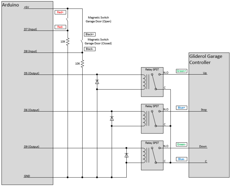
I created an updated circuit with three relays, one for each of the start, stop and down actions. I’ve also included two magnetic switches attached to the rail to determine the position of the door (open, closed, in between).
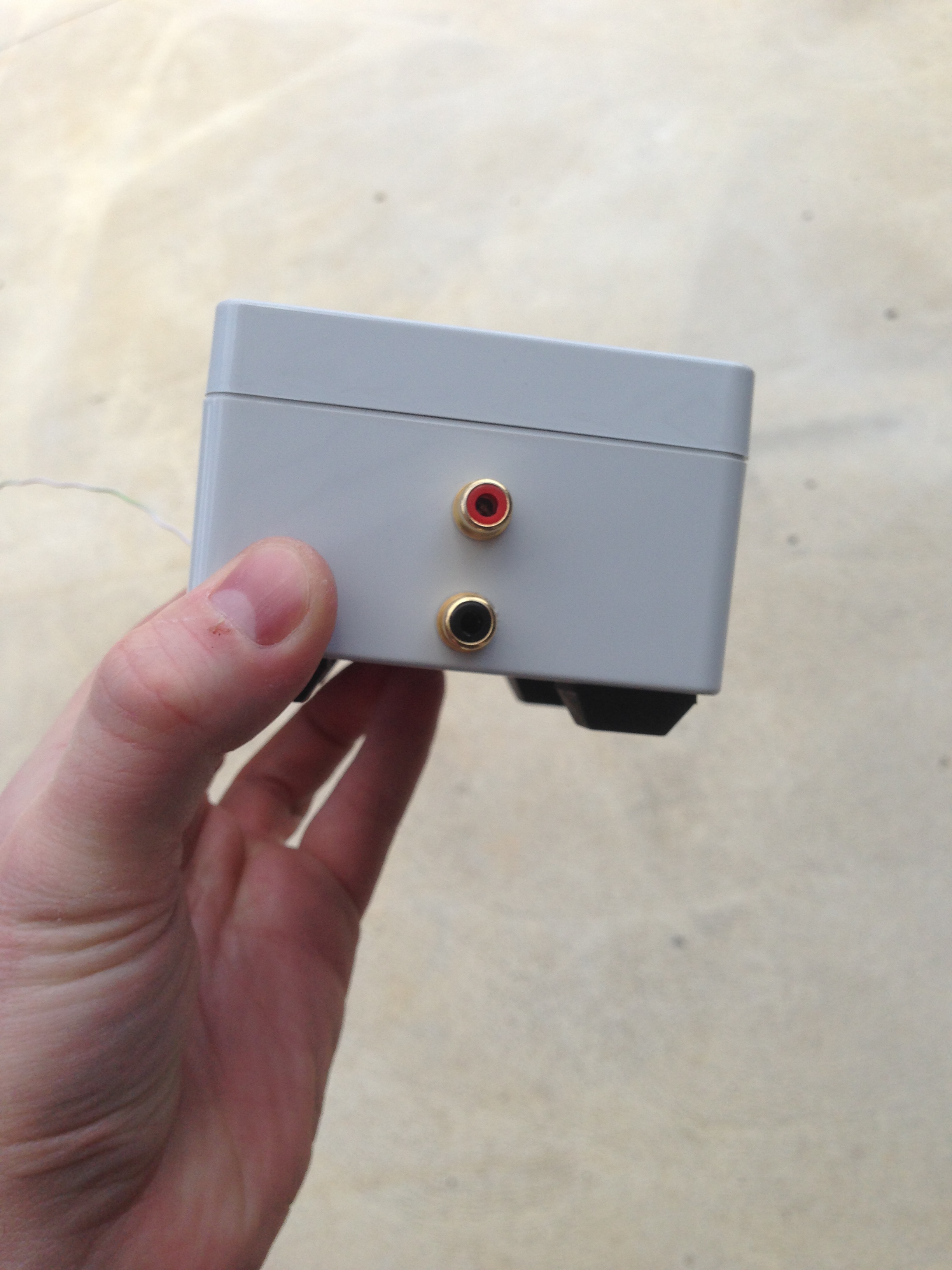
I couldn’t get a standard Arduino enclosure that would hold this circuit, so I ended up buying a generic one and then drilling/filing the appropriate holes in the enclosure.

I purchased some 3mm nylon screws to mount the circuit within the enclosure. An additional board with the relays etc is then slotted into the top of the Arduino board (although not depicted below).

I decided to use RCA connectors for the connections to the switches and controller terminals. I used Red, Black, Green and Blue – and the connectors are depicted in the above circuit diagram.

It didn’t require a significant change in the code from the original version – just another switch to check and a few more relays to energise. If anything, this project was much more an exercise in learning to precision drill/file holes in plastic boxes.
Lots of fun and very useful.
~ Mike

Hi Mike – I have a similar Glideroll Garage door but am struggling to figure out what I should connect the relay to on a similar project. Any chance you could share how you found that information? Thanks
Howdy, do you have a model number, or a photo of the circuit board?