“I suggest a new strategy, R2.” – C-3PO.
In part 3 of the journey towards providing Bluetooth connected audio in my car (integrated with the steering wheel controls), I was experimenting with a Bluetooth audio module that didn’t provide what I needed in terms of functionality. Therefore I ordered a different Bluetooth part from SparkFun, the RN-52.
To recap, the functionality I needed from a Bluetooth audio module was:
- The ability to have the device advertise as a Bluetooth speaker only (as opposed to a hands-free phone device). This would allow the phone to simultaneously pair with my device as a speaker, and the car as a hands-free phone device.
- The ability to control the device name (the name it appears with in the Bluetooth device list).
- The ability to authenticate the Bluetooth connection.
- External analogue audio outputs.
The RN52 those capabilities, and you can even buy it already attached to a breakout board (in order to avoid needing to solder to the surface mount IC directly).
The device has been a little fiddly to get operational, but now that it’s working – it’s doing the job well.
Firmware Update
The first item on the agenda is to update the firmware on the RN52 IC. You can download the firmware from the manufacturer’s website. My device was operating the v1.0 firmware, which has a lot of problems. In order to upgrade it you need to provide a USB connection to the device from your PC. The hookup guide from SparkFun shows you how to provide a USB connection. For me, that meant providing the 3.3V and ground from the Arduino, and providing the USB Data- and USB Data+ from a USB cable from which I’d removed one end. You can also power the device from the USB cable, but I already had power from the Arduino at this point. You then download the firmware update tool and the firmware image from the manufacturer and get started. It only takes a few minutes to upgrade (in my case, to v1.6).
Arduino UART/Serial Connection
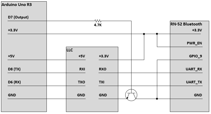
The next item on the agenda is the UART connection to the Arduino. The RN52 provides UART lines that allow you to use serial communications to connect to the device. This is primarily needed for programming the device. Unfortunately, the RN52 is a 3.3V device and the Arduino is a 5V device. In order to connect the two devices to communicate over the serial line, you will need a logic level converter – like this one – to connect the 5V device to the 3.3V device. As you can see in the diagram below, the Arduino is providing 3.3V to the device – to both its 3.3V input and its PWR_EN input. The PWR_EN input is used more or less as an on/off switch. GPIO9, when pulled to ground, puts the device into command mode allowing you to send/receive commands over the UART lines. You can leave it in command state permanently (like I’m doing), or enable it as needed. The UART_TX and UART_RX lines are connected to the logic level converter, so that they are 5V on the Arduino side, and 3.3V on the RN52 side. I then added a NPN transistor (and resistor), so that I can use a digital pin to control the power to the device. Whilst I technically could have used PWR_EN, I wanted the ability to reboot the RN52 device without being reliant on its processor to control its on/off state.
The reason I used D6/D8 (or any other arbitrary choice) instead of the D0/D1 hardware serial lines is because I wanted to maintain the ability to use the Arduino’s USB serial connection to the computer, whilst interfacing serially with the RN52. As such, it means you then need to use the SoftwareSerial library. As a point of reference though, the RN52 defaults to 115200bps for its baud rate. I wanted to drop that down to 9600 before connecting it to the Arduino. You can achieve that by pulling GPIO7 to ground, or by using a configuration command from a serial terminal. The configuration commands are detailed in this file.
Configuration
The configuration of the device is performed through the UART connection. The configuration is very straight forward, and detailed in the the file I provided a link to above. Basically, you need to specify the device name; the authentication type; the profile type – so that you can have your RN52 appear as a speaker, or a hands-free phone device, or both; the device’s behaviour – reboot on connection loss, be discoverable on boot… That’s about it for the device configuration.
I configured mine so that every time it boots, it will attempt to automatically connect to devices to which it had previously connected, turn on discovery mode if it doesn’t find an existing device, and reboot after it loses a Bluetooth connection. Given the device is going to be embedded in the stereo – without a user interface – the reboot option is a good way of ensuring the device is always operating correctly.
Audio
With the device configured, it was time to test. I actually connected everything to the car’s stereo at this point of the test. I was using the rear auxiliary input on my stereo. This, alas, is where the problems started. I was able to get everything working, however I was getting a lot of noise with the music. I wasted a couple of days on this problem thinking it was a ground loop issue, before realising that it was simply a lack of understanding about how analogue audio connections work.
For some strange reason, the RN52 module has 4 outputs for analogue audio – L-/L+, R-/R+ – which is referred to as differential balanced audio. Quite useful if you are sending your audio directly to a left and a right speaker. However, the auxiliary audio input on my car is expecting more or less a headphones connection – which is L/R/GND. I had clumsily assumed that the L- and R- were ground, and connected them together before sending them to the auxillary GND on the stereo. It turns out that was incorrect…
It also turns out that converting from differential balanced audio to a standard headphone connection is not quite as trivial as I would like. You need to use an additional circuit with another IC to make that change. The device that I ended up going with uses a Texas Instruments TPA6112 IC, in a pre-built circuit. I was only able to buy this through eBay from China. I won’t include a link to eBay as the products constantly change, but if you search for “Differential balanced 150mW Headphone Amplifier Board TPA6112” you should find something. This device takes the L-/L+ and R-/R+ as inputs, and outputs an L/R/GND connection – which then gets connected to the rear auxiliary audio input of the stereo.
I’m still waiting for that amplifier module to arrive, at which point I’ll write the final post in the series with the end-to-end circuit, completed and installed in the car.
To be concluded…
~ Mike

2 thoughts on “Eavesdropping on the Single Wire CAN Bus – Part 5: Bluetooth Take #2.”