“1.21 gigawatts! 1.21 gigawatts! Great Scott!” – Dr. Emmett Brown.
Ahh, Back to the Future. Dr Brown’s reaction after learning of the recent changes to the non-functional capacity requirements.
This post is part of a 6 part series, starting with Part 1.
I had a tremendous amount of fun with that first system, despite its simplicity. What I needed to do now however was modify the system to allow me to determine if the garage door was open or closed. I did some more research on the BOL6 controller only to learn that even though the garage controller knows the state of the door, it’s not going to tell me. Short of pulling the unit apart and soldering directly onto the motherboard, none of the provided terminals could give me the information I sought.
So, Plan B. B for bring your own sensor. Given there was no suitable way to ask the Garage Controller for the status, I needed to create my own. This time I looked at the magnetic reed switch option, similar to those used in alarm system sensors.
I then needed to find a location to mount the magnetic switch (both the switch component and the magnet component) where they could either detect the door in the closed state, or the door in the open state.

I attached the switch to the arm that pulls the garage door up. Now this switch will let me know when the garage door is either fully open, or not fully open. I can’t technically infer that the door is closed, only that its not 100% open. I could have used a second switch to check if the door was completely closed, but there were very few places to attach the switch. Still, this was sufficient for my needs.
Now that I have the switch, I need to use another Arduino digital pin, but this time an input pin.
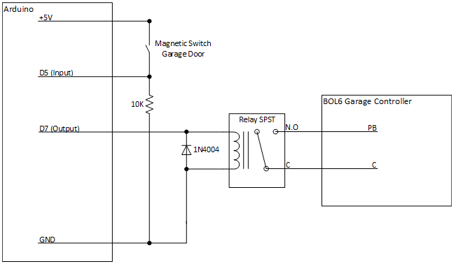
It’s the previous circuit, but now with digital pin 5 being used as an input pin. When the magnetic switch is open (the door is closed), pin D5 will be pulled down to ground through the 10K ohm resistor. At this point, if I execute digitalRead(5) I will see the LOW state. When the magnetic switch is closed (the door is open), the current will flow from the +5V rail through the 10K resistor to ground. The input pins operate with a high impedance, so they have very little impact on the current flow – they can simply detect the voltage on the circuit.
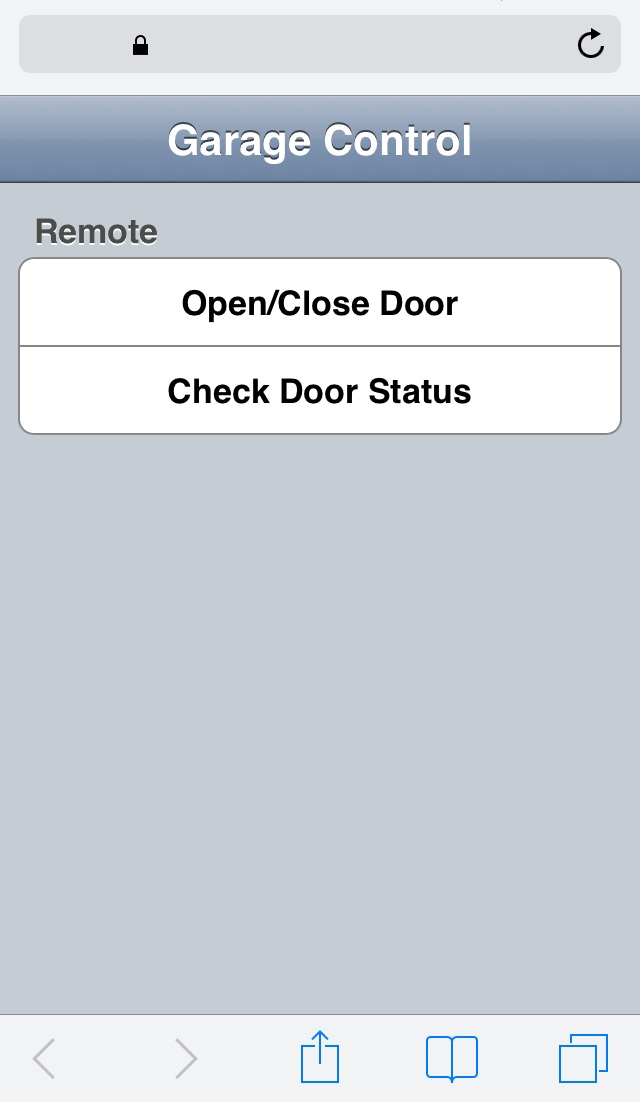
This is the updated web page with the door status button.
Below is the updated code for the loop() function. There are two major changes here. The first change is that the code can now respond to status request packets. The second change is that now the code can determine the state of the door, it can respond with more information during the garage trigger request.
#define PIN_GARAGE_STATUS 5

/***************************************************************/
/* Function: loop()                                            */
/***************************************************************/
void loop()
{
	IPAddress ipClient;
	int iBytesReceived = 0;
	char szBuffer[30];
	String strBuffer;

	Serial.println("loop()");

	// Start Network
	if (!bNetwork)
		startNetwork();

	if (!bNetwork)
		return;

	iBytesReceived = ethUDP.parsePacket();
	// Packet Received
	if (iBytesReceived > 0)
	{
		ipClient = ethUDP.remoteIP();

		// Clear Buffer
		memset(szBuffer, 0, sizeof(szBuffer));

		ethUDP.read(szBuffer, sizeof(szBuffer));

		// Confirm buffer is null-terminated
		if (szBuffer[sizeof(szBuffer) - 1] == 0)
		{
  			// Convert (char *) to (String). The String class has more functionality
			strBuffer = String(szBuffer);

			// Trigger Garage Door
			if (strBuffer == "SignalGarageTrigger")
			{
				Serial.println("Received trigger packet from " + String(ipClient.toString()) + ":" + ethUDP.remotePort());

				// Generate and Send response packet
				ethUDP.beginPacket(ethUDP.remoteIP(), ethUDP.remotePort());
				if (digitalRead(PIN_GARAGE_STATUS) == LOW)
					ethUDP.write("Garage Open Triggered");
				else
					ethUDP.write("Garage Close Triggered");
				ethUDP.endPacket();

				// Trigger Relay
				digitalWrite(PIN_GARAGE_TRIGGER, HIGH);

				delay(200);

				digitalWrite(PIN_GARAGE_TRIGGER, LOW);
			}
			// Garage Door Status
			else if (strBuffer == "SignalGarageStatus")
			{
				Serial.println("Received status packet from " + String(ipClient.toString()) + ":" + ethUDP.remotePort());

				// Generate and Send response packet
				ethUDP.beginPacket(ethUDP.remoteIP(), ethUDP.remotePort());
				if (digitalRead(PIN_GARAGE_STATUS) == LOW)
					ethUDP.write("Garage Door Closed");
				else
					ethUDP.write("Garage Door Open");
				ethUDP.endPacket();
			}
			// Unknown Message
			else
			{
				Serial.println("Unknown packet from " + String(ipClient.toString()) + ":" + ethUDP.remotePort() + " (" + strBuffer + ")");
			}
		}
		// Corrupt Message
		else
		{
			Serial.println("Corrupt packet from " + String(ipClient.toString()) + ":" + ethUDP.remotePort());
		}
	}

	delay(50);
}
That’s it. The code’s been updated, compiled and uploaded back to the board. The additional pair of wires coming in from the sensor has been added to the existing RJ connector and the whole system is working.
It’s a pretty cheap entry into home automation and very satisfying to develop. I’ve built some additional devices since which I’ll add blog entries for later. I’ve now got the air conditioner being controlled by the same system, and an ultrasonic range finder with status lights in the garage to make sure the cars get parked at the optimal distance from the wall.
Hopefully this information can demystify some of the magic behind computer/other electronic device integration. With the advent of the Arduino and Raspberry Pi type devices, it’s becoming much easier to start these kinds of projects at home.
~ Mike

One thought on “Adventures with an Arduino – Part 6: The Project Change Request.”