“Several transmissions were beamed to this ship by rebel spies.” – Darth Vader.
In my most recent post, I tested the Bluetooth module for compatibility to the iPhone – which was successful. I then moved on to the more complex part of the project which was to see if I could capture GMLAN messages on the low speed (33.3Kbps) single wire CAN bus (SWCAN) of the car (Holden VE International). If you recall, the purpose of this was to enable me to listen for steering wheel track change messages, and then to feed those commands to my Bluetooth audio controller causing a Bluetooth song/track change. It took a bit longer to achieve a successful test than I was hoping for as there was very little documentation available and many forum posts with incorrect, misleading or incomplete information.
As such, in this post I’m going to be very detailed in the hope that it helps someone else achieve a similar goal. This post has four key sections – background information, CAN Bus Shield, ODB-II pin-out, and sample code. This post contains all of the information you will need to connect an Arduino with a standard CAN Bus Shield to a Holden VE Commodore International.
Background Information
For reference, the Holden VE Commodore uses a high speed (500 Kbps) and a low speed (33.3 Kbps) bus for connecting the internal systems. The high speed bus is used by the primary vehicle control systems (devoted to the operation of the car), and the low speed bus is used for the peripherals (like the stereo and steering wheel controls). I was able to gather this information from a useful article here. I then used the pin-out guide from here (second table), which indicated that the low speed SWCAN bus is actually on pin 1 of the car’s ODB-II socket – which is a pin not commonly used in ODB-II connectors. That information also lined up with the article mentioned above, so I was reasonably confident it would work. As such, I needed to build a plug with connectivity to pin 1 and pin 5 (signal ground) – and ignore all of the other pins.
CAN Bus Shield
Here’s the key component – the SparkFun CAN-Bus Shield. Even though this shield is designed for high speed CAN, we can drop the baud rate down to 33.3 Kbps and still operate.
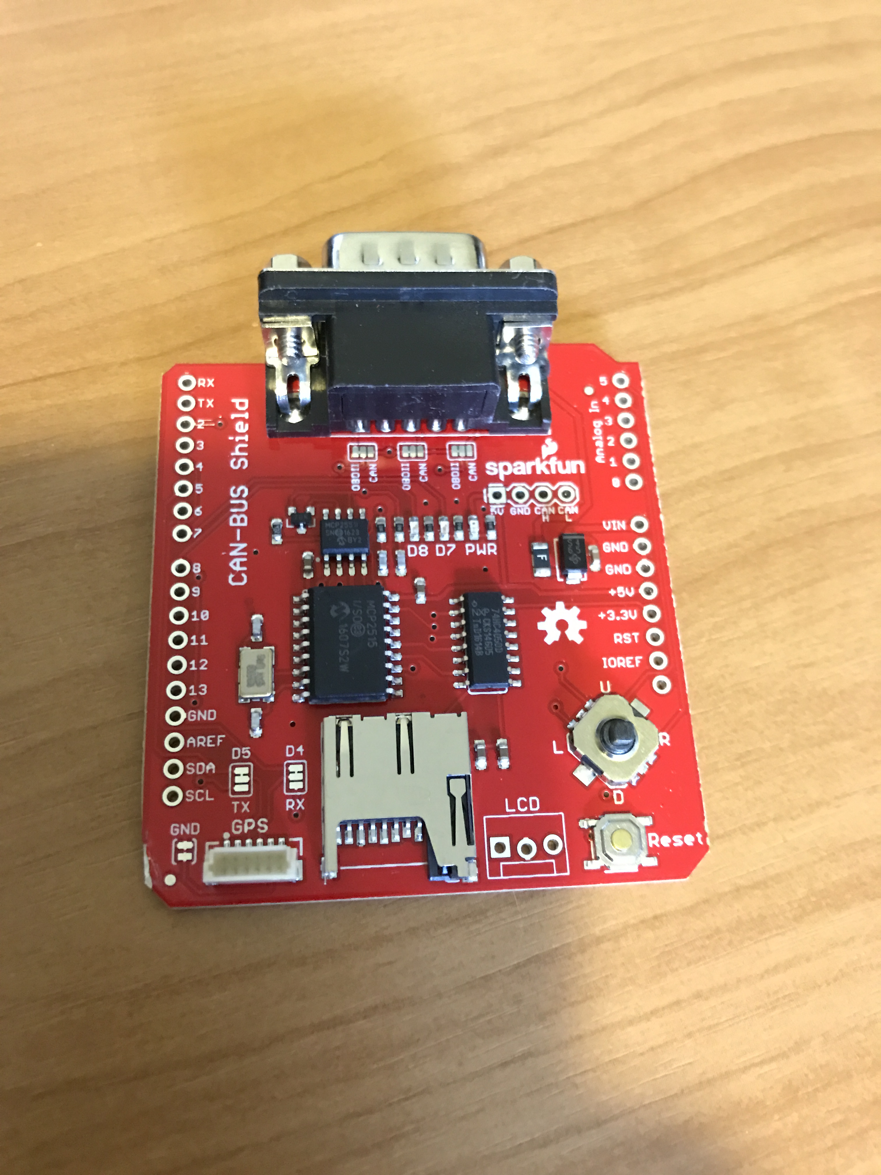
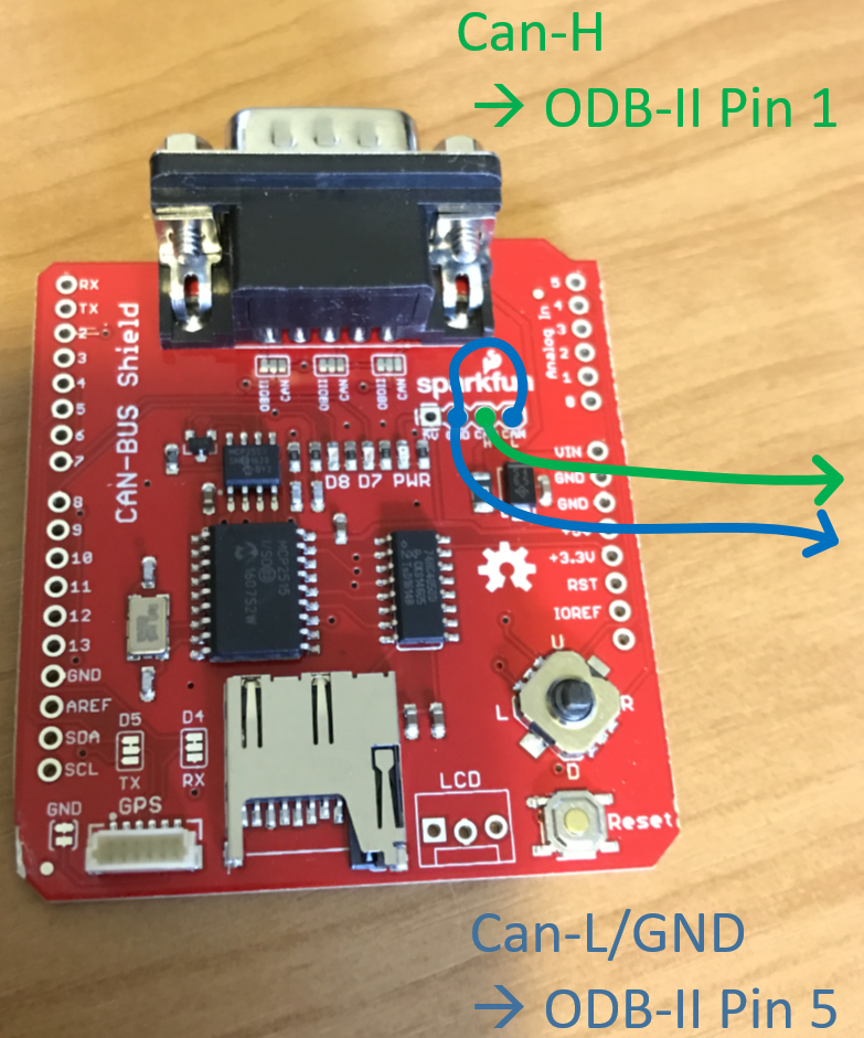
You can ignore the DB-9 connector altogether – the SparkFun ODB-II to DB9 connector doesn’t have the ODB-II pin 1 connection so it doesn’t suit our purposes. We basically need to connect the CAN-H (High) and CAN-L (Low) lines on the shield to the appropriate pins on the car. Luckily, CAN-H and CAN-L are broken out on the shield – so we don’t need to try and connect to the pins on the DB-9. We need to connect CAN-H on the shield to pin 1 (SWCAN) on the car (via the ODB-II plug). We then need to connect CAN-L to ground on the shield and to pin 5 (signal ground) on the car (via the ODB-II plug). So we basically have 2 wires connecting the shield to the car as shown below…
ODB-II Connector
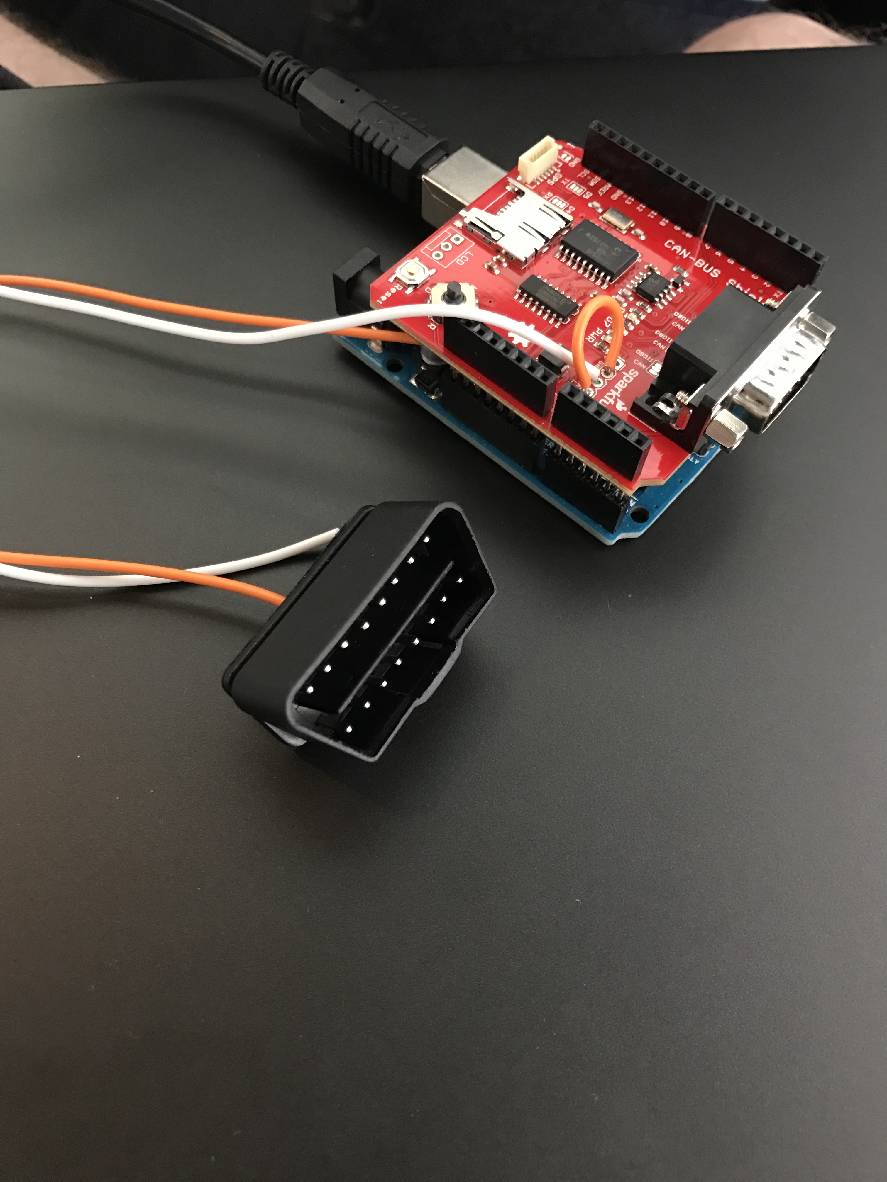
I also bought (a while ago), an ELM327 USB scanner from eBay. I disassembled it and extracted the ODB-II plug which I then desoldered ready for interfacing to my circuit. I connected a couple of leads to pin 1 (SWCAN) and pin 5 (signal ground). That ‘melted plastic’ look was actually like that when I removed it from the ELM327 – honest. White is pin 1, and orange is pin 5.

Here they are side by side. Note, I’m just using a standard Arduino Uno R3 as the base board.
Sample Code
As most of the libraries for the CAN Bus shield do not cater for a 33Kbps baud rate, I ended up finding an alternative library here. I also used this spreadsheet for a reference to confirm that I had identified the correct signals for the steering wheel controls. I opened one of the samples that came with the library, and then tweaked it slightly for the proof of concept. Note in the setup() function, the baud rate is specified as CAN_33K3BPS (33.3 Kbps).
#include <mcp_can.h>
#include <SPI.h>

long unsigned int rxId;
unsigned char len = 0;
unsigned char rxBuf[8];
char msgString[128];

#define CAN0_INT 2 // Set Interrupt to pin 2
MCP_CAN CAN0(10); // Set CS to pin 10

void setup()
{
  Serial.begin(9600);

  if(CAN0.begin(MCP_ANY, CAN_33K3BPS, MCP_16MHZ) == CAN_OK)
    Serial.println("MCP2515 Initialized Successfully!");
  else
    Serial.println("Error Initializing MCP2515...");

  CAN0.setMode(MCP_NORMAL);

  pinMode(CAN0_INT, INPUT);
}

void loop()
{
  if(!digitalRead(CAN0_INT))
  {
    CAN0.readMsgBuf(&rxId, &len, rxBuf);

    // 0x100d0060 = Wheel Controls
    if ((rxId & 0x1FFFFFFF) == 0x100d0060)
    {
      sprintf(msgString, "0x%.8lX,%1d,", (rxId & 0x1FFFFFFF), len);
      Serial.print(msgString);

      if((rxId & 0x40000000) != 0x40000000)
      {
        for(byte i = 0; i < len; i++)
        {
          sprintf(msgString, " 0x%.2X", rxBuf[i]);
          Serial.print(msgString);
        }
      }
    }

    Serial.println();
  }
}
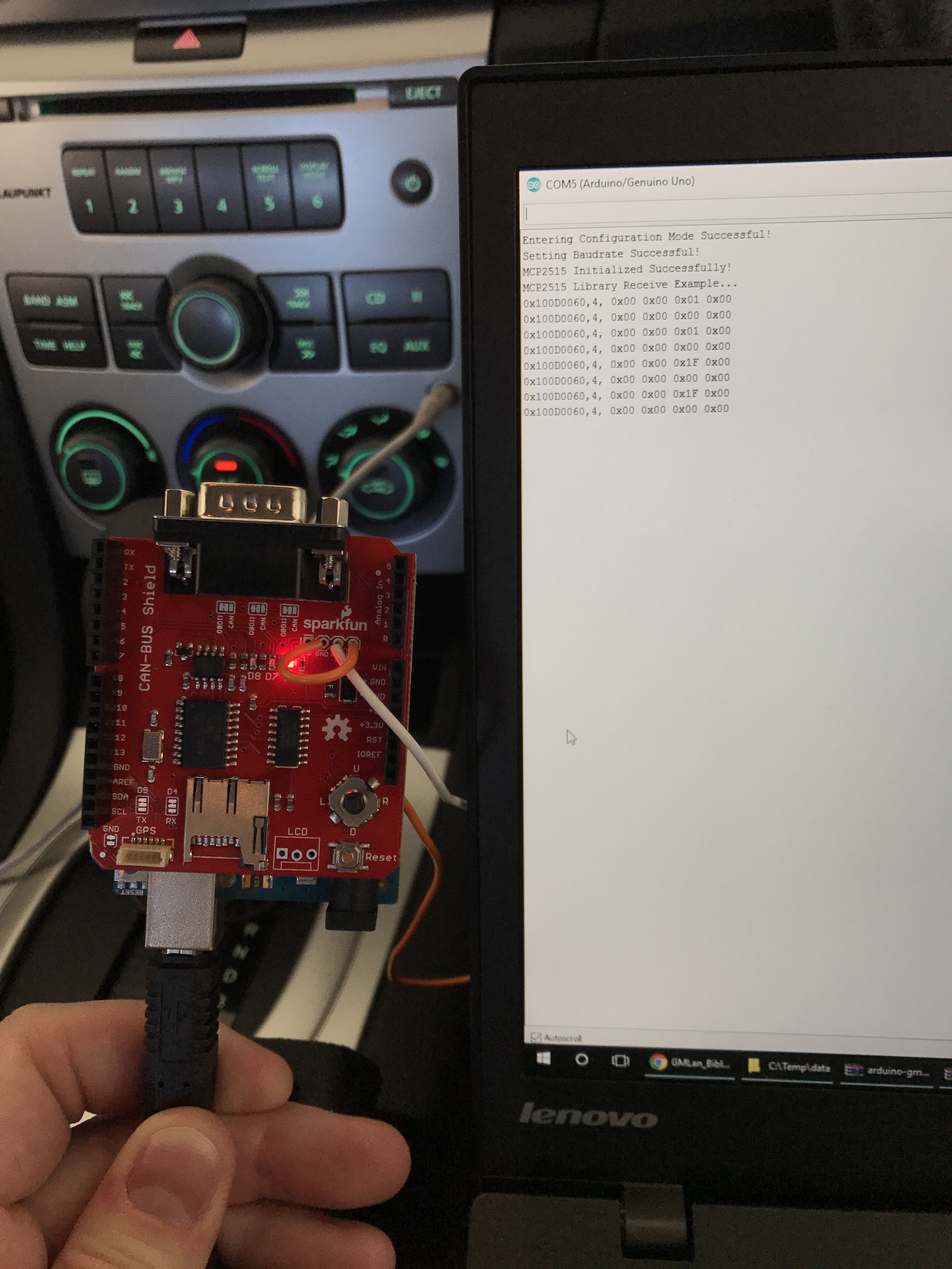
I connected it all together, turned the ignition on (for the stereo) and started using the track up/down buttons. As you can see in the screen below those messages were identified and displayed. The code itself is pretty messy as its one of the library example files tweaked slightly to ignore any messages not from the steering wheel (messages with an ID of 0x100D0060). It looks like the shield (the controller on the shield specifically) can be configured with its own filter to help me capture just the messages I’m looking for, but I’ll worry about that in a later build. For now, I’m just ecstatic that I can see the messages coming in.
For reference, and this is described in the spreadsheet, I’m receiving 4 byte messages (4 bytes of data anyway) like this: 0x00 0x00 0x01 0x00. The 0x01 indicates the track change wheel has been clicked up once. If I clicked it up a few times in quick succession, that 0x01 would be something like 0x03 (for 3 clicks). Likewise, a 0x1F indicates a single downward click, and a 0x1E indicates two downward clicks (counting down from hexadecimal 1F). A message of 0x01 0x00 0x00 0x00 would indicate the track change wheel had been pressed (its also a button). I’m going to use that for play/pause.
With that sample code running, any other button press on the steering wheel should display a message on the screen as well.
With the Bluetooth and the CAN Bus now operational, I can put the complete prototype together and integrate it with the car. If the prototype is successful, I’m going to rebuild the device and mount it inside the stereo itself. The stereo has a lot of empty space inside with access to power, the CAN-H line (as the stereo is connected to the low speed CAN bus as well), and the AUX audio input. As such, the entire device will be self-contained in the stereo with no external cables.
Exciting times. On to Part 5…
~ Mike

I really hope that you’ve saved me a little bit of googling, previously i ordered the same canbus board you have as shown above.. Now to find it again (most likely still in my glove box)…
But seeing a you got yours working, you’ve given me some motivation to maybe tackle this again on the weekend…
Lets hope my 2004 WL V8 Caprice does truly have the same gmlan..
— A random thank you for blogging this.
Hey, good luck. Hopefully it’s the same bus and pinout!
Hey, well it turns out that im running J1850 VPW… I remembered that after i assembled my obdII adapter (i got the one with no legs,,, that was wasted time unsoldering them from a dead board)..
I have a elm327 IC floating around in my shed that i originally purchased, so i think it is time i find that and try it again.. The pinout did match, but yea i’ve got a 41kpbs speed or similar (cant remember at the moment). But either way your post still reminded me to get back onto it.. My next project is trying to customise the DIC interface.
Awesome, always good to find the inspiration again! Good luck!
Hi Mike, could you please explain which function do you use to read a particular steering wheel control command? In particular, with the if ((rxId & 0x1FFFFFFF) == 0x100d0060) you filter all the incoming messages from the steering wheel controls but how do you select a particular action like, for instance, the volume up? Please help me.
Thanks for your time.
Howdy, in the example above, rxId is used to determine where the message originated (in this case – the steering wheel controls 0x100d0060). rxBuf then contains the data of the message itself. I then look at the data to determine if its a track up, track down, track enter, volume up, volume down command etc.
Oh, that’s right. Thanks a lot.
Mike, first off, outstanding job writing all of this up! I was locked in from the beginning. I had already found several of the resources you linked, such as the GMLAN bible and a couple others. That is going to save a lot of time when it comes time for me o do my project.
Here is my idea… (I’m not a good writer so bare with me) I will be replacing my stock stereo (2008 Silverado) with a Raspberry Pi with XBMC on it for a headunit. I haven’t decided which way to go next…a secondary RPi or Arduino for a GMLAN control board or build the functionality onto the XBMC RPi (it’s going to be dependant on CPU load an such after some testing). With the XBMC RPi I will be building a program to read engine codes, as well as an app for HVAC. Essentially the app will just send commands to the GMLAN either directly or the controller board (whichever route I go). The plan is to remove the Stereo and HVAC hardware controls completely and move it all to touch screen. I would also have reverse cam and various other features. What would be cool is if I can also bring in some OnStar functionality for free, such as remote start or door unlock from Internet. The RPi will be connected via a cellular shield so that I can also have Navigation via Navit package.
Do you have any thoughts about using a single RPi setup vs a dual RPi or Arduino combo for the GMLAN communications, as well as any knowledge of wiring up a plug to do both GMLAN and diagnostic codes. I’d also love to talk offline if you’d have some time for me to pick your brain about this a little more. Not sure if you can see the email I’m posting from here, let me know.
Hi friend! Amazing job you´re doing!
I have one Commodore VE here in Brazil, that after a lot of research I was able to install the Holden IQ from VE series 2 into my VE1.
Now I´m trying to find a way to remove the grayed out DVD On/Off option from the head unit.(Into the security lockouts in the stereo´s options)
Do you know how to do it, even it I need to buy a specific scanner to do it? This is driving me nuts, there is nobody that wants to share this knowledge, even after the car not being currently in sale anymore!
I appreciate if you can help me with it – thank you in advance.
Hello Assis,
I came across your your request here while researching mikes blog on the Arduino controller for my garage door. Firstly thanks to Mike J McGuire for the initial post and second an apology for the hijacking of the post. Now Assis firstly you do have the required CANBUS diagnostic lead? If you DO have it or even if you do not have the compatible lead please feel free to contact me via a return comment here because I will be able to help you out with some or maybe all that you request.
Thanks Robert.
Hey Robert! I´m very happy to read your reply! 😀
I have a obdscan MX – that is advertised to be capable to access the GM SW-CAN.
I´ve downloaded some softwares to “sniff” the network like the canhacker v2.00 – but…maybe now the challenge just started 🙂
Thank you for your time to help me with it!
Hi Robert! Just replying again- not sure if you noticed the previous and old reply.
I really apreciate any help in this subject – thank you!
Hi,
How can i send messages into the CAN network?? im triing to send messages using the Library https://github.com/coryjfowler/MCP_CAN_lib but Arduino always displays fail.
Capture works OK,
Setting Baudrate Successful!
MCP2515 Initialized Successfully!
MCP2515 Library Receive Example…
Standard ID: 0x100 DLC: 0 Data:
Standard ID: 0x626 DLC: 8 Data: 0x01 0x01 0x00 0x00 0x00 0x00 0x00 0x00
Standard ID: 0x626 DLC: 8 Data: 0x01 0x10 0x00 0x00 0x00 0x00 0x00 0x00
Standard ID: 0x440 DLC: 8 Data: 0x00 0x94 0x6C 0xFF 0x00 0x30 0x20 0x07
Send Fails:
Entering Configuration Mode Successful!
Setting Baudrate Successful!
MCP2515 Initialized Successfully!
Error Sending Message…
Error Sending Message…
Error Sending Message…
Error Sending Message…
Same problem in Sparkfun Canbus Shield and using a MCP2515_CAN board 16MHZ
Any idea? Thanks in advice
it’s for GM-LAN Opel Astra H 33.3KBPS
Hi Arbe
Do you have a solution for this problem or not
thanks
Hi, no. But the sending menssage works, instead in the console shows Error sending message…
I found some ways more easy than Arduino, Like Raspberry pi, or the opcom interface .
Whith raspberry pi, you can use https://www.sg-electronic-systems.com/can-bus-dual-v2-1-shield-for-raspberry/
Using opcom, you can use this VM: https://bugs.lwpm.eu/task/182 (use google translate)
Sending and capture data using a raspberry pi is more easy.
And this playlist its very interesting: https://www.youtube.com/playlist?list=PLNiFaO8hU1z0o_6DSxk-jcVAM3UCUR-pY
Hey Mike,
I just wanted to say thank you for this write up. It’s really helped me along in understanding GMLAN. I had a question that I’m hoping you could answer, just so I can further understand how both the car’s OBDII port and the Sparkfun shield work. Why is it that both CAN L and Ground are connected to the same pin (pin 5) on the car? How does this work?
Hi Mitchel, I’m glad you got some value from the article!
Pin 5 on the car represents signal ground. For the shield and the car to communicate, they need a common ground, so the ground from the shield is connected to ground on the car. My car uses single wire can (SWCAN). For that shield to work with single wire can, it needs its can-l connector pulled down to ground.
Thanks for info Mike! Really appreciate it.
Hi,I read your new stuff named “Eavesdropping on the Single Wire CAN Bus – Part 4: GMLAN (Holden VE Commodore SWCAN). – Hopefully Helpful Hints // Mike J McGuire” like every week.Your humoristic style is awesome, keep doing what you’re doing! And you can look our website about free proxy.
Hi Mike,
Thank you for your posts there has been a lot of useful information here and i want to achieve the same thing for my car and trying to get my head around the coding and howto, a bit of a slow process.
I have a bluetooth adaptor plugged into my aux port on my radio but just missing the steering wheel controls.
i was thinking of doing a similar setup as you so i have purchased a canbed with built in arduino
https://www.longan-labs.cc/1030008.html
and a HC05 bluetooth.
However the HC05 seems to only do bluetooth serial to my phone – no other profiles associated to it.
I didn’t want to spend the money on the RN52 as i don’t need audio as i’ve already got it with my other adaptor. Do you have any recommendations on what bluetooth module to get?
i was hoping to 3d print a case to house this canbed, bluetooth module with a odbport so i can just plug it in the obd port to power up, i connect my phone to both bluetooth devices and have steering wheel controls – thats my ultimate goal
Is there any chance of some more sample code on how you parsed the steering wheel messages and used it to send commands via bluetooth to your phone to skip / pause? i’m really struggling here as this isn’t my realm
Thank you
Howdy Steven – I’m not sure that you could send track change messages via a bluetooth adapter that is not using an audio profile, where as it was quite simple with the RN52. I’d suggest moving to something like an RN52, and replacing the existing bluetooth adapter you use. You do then need to get the audio out of the RN52 to the aux port of your car.
https://docs.google.com/spreadsheets/d/1qEwOXSr3bWoc2VUhpuIam236OOZxPc2hxpLUsV0xkn0/edit#gid=1
The link above is to an XLS that shows the commands for the wheel controls (on tab 68 wheel controls). Those were the messages to look for. The trick though is that the next track message actually varies based on how many times you’ve sequentially hit the next track button.
Good luck!
Thankyou for your reply Mike,
I just purchased the RN52 as i wasn’t getting anywhere with the HC05 – i could flash the HC05 but not worth the effort.
I think i’ve now figured out how to use the bluetooth profile and send the command to my phone to skip the song on my phone and will test when my rn52 arrives.
now just to get my head around coding lol
thank you for the tip about next track message – So if i push next track 5 times in quick succession it counts up, and if i just push next track once every 5+ seconds it’s normal? or does it keep counting until the car has been switched off?
thank you
if you push times in quick succession you’ll get a single message with a 5 at the end. If you pushed once every 5 seconds you’d get a single message each time with a 1 at the end.
Hi Mike
I have problems like ARBE, I can send the volume up / down packets to the radio. it still receives the packet and displays the volume up status on the screen. but on the arduino monitor it still displays Error Sending Message …
and with other packets like window scrolls, the vehicle has no response. Have you encountered this problem, please help me.
thank you
Hi, if you can do what I have read in these posts then you are the miracle man I have been looking for.i an trying to get a factory tripple SIC Atari guage to display oil pressure on my 2010 be commodore Omega which has a 3.6 Lt LY7 V6 engine in it with factory fitted LPG. The SIC gauges are out of a clubsport and the volts and engine oil temp work but not the oil pressure.Can you help please…?
Sorry, stupid me not proof reading before posting,it should say VE not BE